
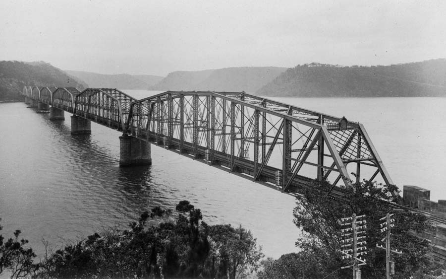
When the first railway bridge over the Hawkesbury River was opened on May 1, 1889, it completed the final link in a rail system that linked NSW with South Australia, Victoria and Queensland – albeit not with uniform gauges.
The rail line that linked Homebush (now known as Strathfield) with Waratah had been one of the toughest pieces of railway engineering yet tackled in the Australian colonies (Australia as a nation had not yet materialised). With river crossings to make and tunnels to dig through hard sandstone, the line between Homebush and Hamilton is said to have cost more than £1.6 million or about £12,000 per kilometre. This doesn’t count the Hawkesbury Bridge itself (which cost another £340,000) nor the £360,000 section of track from the north bank of the river to Gosford, inlcuding the Woy Woy tunnel, lined with 7 million bricks.
Considering the first railway in Australia – from Parramatta to Sydney – had been built just 34 years before, the railway construction boom from that time up until the opening of the Hawkesbury Bridge is little short of astounding.
In later years many people wondered why the bridge builders had chosen such a difficult site, when they could have built two short bridges from bank to bank via Dangar Island. In a 1956 interview reported in The Newcastle Sun, the NSW Railways chief civil engineer who built the second Hawkesbury bridge in the 1940s, General Fewtrell, said his reading of the reports of the original bridge surveyors persuaded him that they were afraid of attack by Aboriginal tribes on one side of Mullet Creek and preferred to stick to the other side.

Tenders closed for the bridge in 1885. At the time the proposed bridge was a massive undertaking. One of the piers was the deepest yet attempted. Fourteen tenders were accepted from around the world, with the Union Bridge Company from the USA the successful tenderer.
The piers themselves were a huge undertaking. The plan was to dredge silt and mud from three cylinders in a caisson. The steel was left to rust over time, leaving a solid concrete pier. The sixth pier was 50m deep, but still didn’t strike a solid base. The fifth pier was out of line, and efforts to correct it were plagued with trouble. By the end of the job the contractors, who lost heavily on the job, had to build coffer dams around each pier.
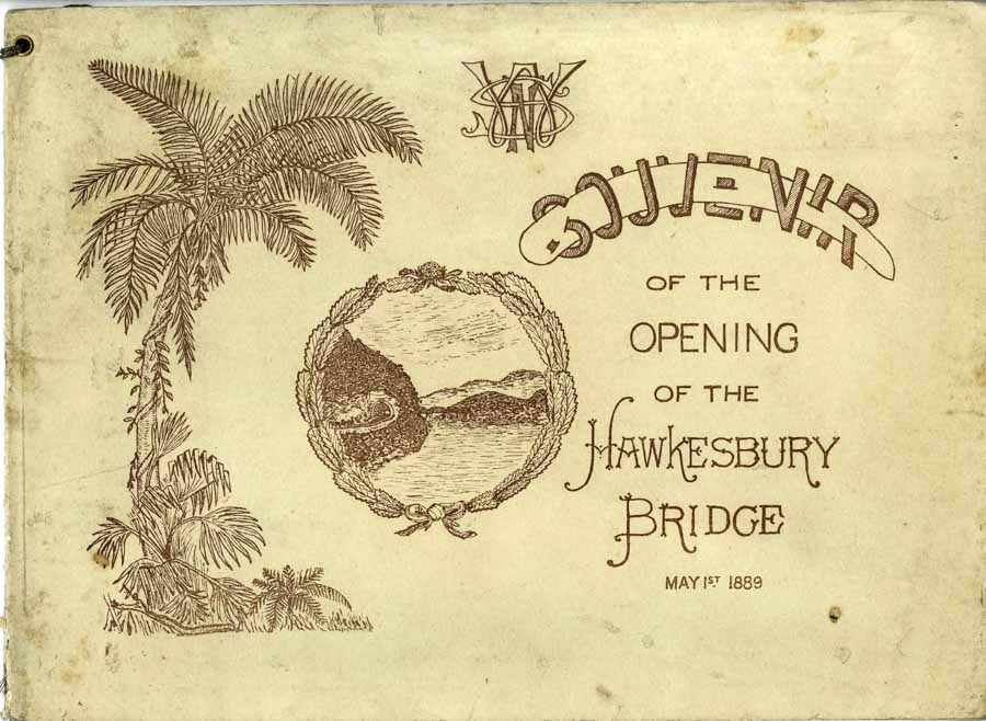
The following paragraphs in italics are slightly edited from a brochure issued at the opening of the bridge in 1889. The imperial measurements have been converted to decimal.

The caisson for each pier is rectangular in form with rounded ends, 1.4m by 6m splaying out 60cm wider all round at the bottom. The main outer skin is 1cm steel; inside this are three wrought-iron dredging tubes, arranged on the longitudinal centre line of the caisson and connected with it by angle and T steel strutting. The dredging tubes splay out in a trumpet mouth at the bottom, meeting the outer skin and each other in strong steel cutting edges.

The top of the caisson as built is open, and exhibits the holes for dredging as described, which are 2.4m in diameter, and 4.2m apart from centre to centre. The spaces between them and the outer skin were filled with concrete, as the mud in the tubes was removed by dredging, thus causing the whole to descend through the deep mud of the bed of the river, until the caisson rested on the firm bottom beneath. The wells or tubes were then also filled with concrete, making a solid mass entirely below water, on which the masonry piers were erected. The first section or ring of the caisson was, in each case, built up on shore, and towed out to position, and sunk to the bottom of the water, when dredging was begun, and successive rings added as the descent proceeded.
The masonry of the piers, of which the plinth is made, is hard trachyte from Bowral, and the upper part local sandstone. The abutments are entirely of sandstone. The south abutment was started in March 1887, and the north abutment in May 1888 and were ready for superstructure in April 1888, and September 1888, respectively.

Steel for the bridge spans was rolled in Scotland, sent to the USA for “up-ending” then sent back to Scotland where they were assembled, checked and then dismantled again for the voyage to Australia. The seven spans were reassembled on a stage on Dangar Island then floated to the piers on a huge pontoon. Gales and fouling caused many problems for the workers trying to put the spans in place. When the last span was being positioned in 1889 it became locked with the adjoining span and only good luck averted a disaster.

The length of the bridge between the abutments was, according to the original design, 883m but in consequence of the caisson of pier No. 6 getting out of position the length of span No. 6 was increased 1.4m.
A large pontoon, 102 in length by 18m wide and 3m deep, was constructed, with a staging upon it sufficiently high to enable the girders to command the piers when the pontoon was floated out at high tide. The girders, being 125m long, overhung the pontoon, the length of which had to be regulated by the minimum water space at the abutment spans. When the pontoon, which was provided with forty-four water-tight compartments, was complete with its staging, it was towed over a gridiron of piles and sills, in shallow sheltered water, and sunk, the exterior and interior valves of the compartments being all left open so that the water ran freely in and out at all tides. The complete span was then put together on the top of the staging. This operation of erecting each span is shown on the first of the accompanying illustrations. The roadway girders, and all but the sleepers and rails, were placed in position, except on the overhanging portion, which was lightened and temporarily strengthened. This done, at low water of spring tide, weather being favourable, the valves were closed, and as the tide rose the pontoon floated, and was conveyed by 15cm hawser extending from Dangar Island (where the pontoon lay) to the bridge, and running over a winding engine on the pontoon; this being aided by a steam-tug and the flowing tide. This operation of floating a span in position is shown in the second illustration.
When the pontoon had reached the proper position it was moored between the piers, and allowed to fall with the tide, leaving the girders in place on the piers ; the pontoon was then brought back and placed there to the gridiron, at the next high tide, and the same cycle of operations was repeated. This operation was carried out with varying but ultimately successful issues in all cases; spans Nos. I, 6, and 7 having been from adverse weather the most troublesome. The roadway was completed on April 23rd, 1889, and the bridge was tested on April 24th by two trains, making up a total weight of 925 tonnes, one being placed on each road on each span in succession. The deflection of the main girder in every case was 5.7cm.

NSW Premier Sir Henry Parkes observed at the bridge opening that the completion of the link was a major step towards the great goal of federation of the colonies into a new nation.
On the day of the opening two special trains left Newcastle and stopped at the bridge’s northern end. Then the special trains arrived from Sydney and crossed the bridge with Governor Lord Carrington and 650 other dignitaries aboard. The Governor officially opened the bridge on the northern end, then the trains formed a procession to Brooklyn Station.

The pontoon that had been used to lift the spans into place was turned into a banquet hall for the guests, who sat down to eat after taking a short sightseeing tour aboard the vessels Thetis, Premier and General Gordon. The General Gordon had been used until that day to carry rail passengers across the river.
The bridge functioned well enough for some years, but in time it emerged that the concrete used was not of the highest quality and a collapse was feared, especially as trains had become bigger, heavier and faster over time. Serious cracking in 1937 led to a major review, and it was decided the bridge would have to be replaced.

By this time train speeds over the bridge had been reduced to just 8km/h or less and the “down” line had to be closed, making the bridge a single lane and producing delays for vital transport.
.
I remember as a child, trains crawling across the original bridge, and spans assembled on one of the banks, being floated into position on their new pontoons.
Interesting that there are actually station platforms on both sides of the river. On one trip my train picked up a worker from the northern platform to drop him off on the other side. How else would he have crossed the river?
I remember as a child, trains crawling across the original bridge, and spans assembled on one of the banks, being floated into position on their new piers.
Interesting that there are actually station platforms on both sides of the river. On one trip my train picked up a worker from the northern platform to drop him off on the other side. How else would he have crossed the river?